This machine is suitable for high temperature and instantaneous sterilization of liquid materials such as milk, soy milk, fruit juice, etc. It has the characteristics of high efficiency, energy saving, simple operation and good sterilization effect.
1. Product model and name
UHT type ultra high temperature instant sterilizer
2. Purpose and scope of application
This equipment is suitable for instantaneous quenching of liquid foods such as fresh milk, fruit juice, beverages, popsicles and ice cream slurry, soy sauce, soy milk, condensed milk, alcohol, etc. Bacteria can also be used for the sterilization of fluid medicines, and the effect is very significant.
3. Main structure and working principle
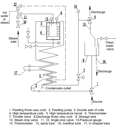
The structure of the ultra high temperature instant sterilizer is shown in Figure 1. A pressure vessel, a high temperature barrel (5), is installed in the main unit for filling Pressure steam. The main setting outside the barrel is a spiral double sleeve (3), which is used for the cold and heat exchange of incoming and outgoing materials; the main setting inside the barrel is a spiral single tube (4), which is used to receive heat indirectly.
Figure 2 depicts the sterilization process of the material. The material enters the outer flow channel of the double coil pipe (3) through the feed pump (2) and is preheated by the indirect heating of the hot material flowing out of the inner layer. When the material enters the high temperature set in the high temperature barrel (5) When the coil (4) is indirectly heated by the steam in the barrel, it is heated to the required sterilization temperature, and then the single coil outside the barrel is kept warm to kill the bacteria of the material. When returning to the double coil (3) ), the material enters the inner flow channel and is cooled by the outer cold material, so that the discharge temperature is significantly reduced (generally lower than 65°C). If it is necessary to increase or decrease the discharge temperature in the process, the angle type shut-off valve (12) can be activated to connect the heat source (steam) or cold source (water, or ice water, etc.) to the lower end of the double sleeve. Outer runner.
The throttle valve (7) can be adjusted. On the one hand, the material is maintained under a certain pressure and the boiling point temperature is increased to prevent Desalination; on the other hand, it is also used to adjust flow. The material will be discharged through the three-way cock (8) after the final product. The lower end of the cock is connected to the coil (15), and its outlet faces the storage tank (9). When necessary, the coil can be rotated to turn the overflow pipe (16). The upper end of the feed three-way cock (1) is connected with the storage tank (9), and the lower end is connected with the material source pipeline.
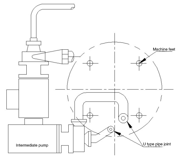
When the processing capacity needs to be improved, the “U” tube (17) can be removed to modify a centrifugal pump, the connection method is shown in Figure 3.
This machine is a hand-controlled sterilizer, and the sterilization temperature is adjusted by the angle cut-off valve (11) (see Figures 1 and 2). The discharge temperature can be changed by the angle shut-off valve (12). The steam pressure gauge (13), the sterilization temperature gauge (6) and the discharge temperature gauge (14) are all installed on the host.
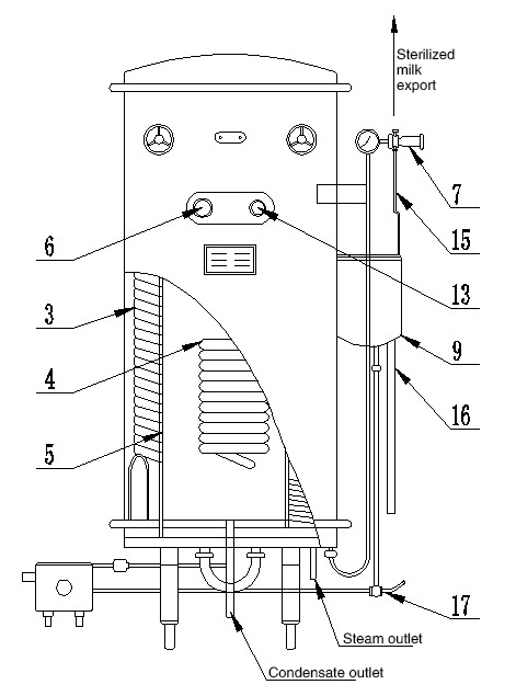
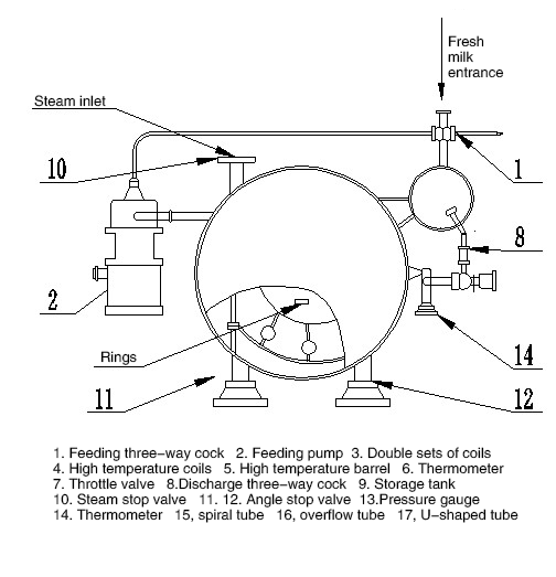
Figure 1, UHT Sterilizer Appearance and Structure Installation Drawing
5. Lifting installation and adjustment
This equipment has two rings on the high-temperature barrel for hoisting purposes, but you have to lift the top cover to see it ( see picture 1).
1. The equipment is placed on the flat floor of the workshop without equipment foundation.
2. When the equipment is installed, 4 supporting bolts can be adjusted, and the supporting feet must be in contact with the floor. The 4 feet of the feed pump are also required to be the same as the floor. Contact, the pump shaft must be leveled to prevent vibration during use.
3. All pipes connected to this equipment should be careful not to subject the equipment to any external force, especially to eliminate the influence of thermal expansion.
4. The feed pump must ensure the correct rotation direction of the motor: the operator faces the impeller, and the pump shaft should rotate counterclockwise and install it well Afterwards, the pump shaft can be turned by hand to see if it is flexible.
5. At the steam inlet, a 0.78MPa (8kgf/㎝²) safety valve must be installed.
6. When using a homogenizer, the pipes connected by the user should be tested at 14.7MPa (150㎏f/㎝²) pressure. leakage.
7. The overflow pipe in the storage tank should be connected to the trench to prevent the washing liquid from corroding and damaging the surface of the workshop.
Figure 2. Sterilization schematic diagram
6. Installation drawing
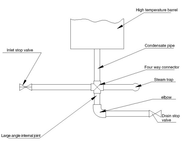
The general installation diagram of this equipment is shown in Figure 1, and if an intermediate pump is added for operation, see Figure 3; when this equipment is used in areas with frequent power outages , Please add “power failure cooling device”, see Figure 4.
Figure 3 Intermediate pump connection diagram
Figure 4 Power failure cooling device
7, Operation and use
1. Check before use
(1) Whether the safety valve and pressure gauge are damaged or malfunctioning
(2) Whether the pipeline of the equipment is unblocked
(3) Whether the flow direction of the discharge three-way cock is downward (that is, to the overflow pipe).
(4) Whether the coil is aligned with the overflow pipe in the storage tank.
(5) Whether the storage tank is full of water.
2. Normal operation
(1) Open the clear water valve on the storage tank (user-connected)
(2) Turn the handle of the feed three-way cock (1) to inject clean water into the feed system
(3) Start the feed pump (2) Use water as a substitute and discharge operation
(4) Open the steam valve (10), control the angle stop valve (11), pour steam into the high temperature barrel (15), and observe the pressure The value of the meter and the temperature meter, and the regulating valve (11), make the temperature meet the requirements.
(5) Close the clean water valve, and when the water in the storage tank is exhausted, change the feed three-way cock (1)
the feeding position: Let the material enter the feeding pump.
(6) When the coil discharges the material, turn the coil to make the material flow into the tank (9), and at the same time change the discharge three-way cock (8 ) Position to start discharging.
(7) Observe the temperature of the sterilizer and adjust the angle-type shut-off valve. For heat-sensitive materials, the steam pressure should be gradually increased to prevent excessive temperature from causing accumulation. Dirt and clogging.
(8) Control the throttle valve (7) to correctly grasp the required “back pressure” to ensure the continuous flow of materials in the pipe. The level of “back pressure” depends on the heating temperature.
(9) When the process needs to increase or decrease the discharge temperature, an angle stop valve (12) can be used.
3. Abnormal operation
(1) If the material pipe cannot be supplied temporarily, fill the storage tank with clean water first, and then align the coil with the overflow pipe. When the last material passes through the feed three-way coil (1), switch The handle allows the water substitute in the storage tank to enter the feed pump (2). At this time, the clear water valve on the storage tank should be opened to ensure the clean water circulation when the material is interrupted. When the material is supplied, it will resume normal operation.
(2) If the material is stopped for a long time, the steam angle valve should be closed first, and then the water can be circulated for a few minutes according to the above method, and then shut down and stop running .
(3) Cleaning of equipment
This equipment uses in-situ chemical cleaning (C, I, P). Do not disassemble the parts during cleaning. The purpose of cleaning is to remove the heat exchange plate wall. To improve the heat exchange effect and improve the equipment capacity. Under normal circumstances, it must be cleaned once after 6 to 8 hours of continuous use. In special circumstances, if the production capacity is found to be significantly reduced, it should be cleaned immediately.
(1) C, I, P washing program
a. Washing:
When the material is about to end, it is washed with water to remove residual materials and at the same time it is more conducive to the next clean water cleaning. When the water flowing out of the equipment becomes clear, the washing can be stopped.
b. Alkaline washing:
Prepare caustic soda (caustic soda NaOH) into a 2% alkaline detergent in a storage tank, heat to 80°C, and circulate for about 30 minutes . The lye can dissolve protein, milk fat, and foam and loosen deposits. If the fouling is serious, the concentration of the solution can be appropriately increased.
c. Washing:
After draining the lye, rinse with water for about 15 minutes.
d. Pickling:
The nitric acid (HNO3) is formulated into a 2% acid detergent, heated to 80°C, and circulated for about 30 minutes.
e. Washing:
After removing the acid, rinse with water for about 15 minutes to prevent the material from being contaminated by residual acid during reproduction.
After rinsing, fill up with clean water for the next operation.
(2) Precautions for washing:
a. In the washing process, do not use chloride to prepare detergent.
b. Clean water requires a chlorine content of less than 50mg/L. In areas with poor water quality, the water must be purified during washing.
8. Maintenance, maintenance and troubleshooting
1. Regularly check the steam trap to prevent the condensed steam from being blocked.
2. Frequently check whether the safety valve, pressure gauge and temperature gauge are malfunctioning.
3. If a serious leakage of the feed pump is found, it should be repaired in time, and the section shaft seal should be replaced if necessary.
4. If used at the same time with a homogenizer, it can be used as a 3WR-1.5 high-pressure pump, and maintain it according to the instructions.
5. If the equipment is used in areas where there is a possibility of freezing during the winter period, the water in the pipeline should be drained or 1% The lye fills the tube.
6. The joints and cock of the pipeline should be checked frequently to ensure that they are not leaking or mixed with air. Because the air brought into the material will accelerate the formation of tube wall fouling.
7. When the equipment is not in use, the steam valve should be opened for future use.
8. The motor bearing of the feed pump should be cleaned every year and the lubricant should be replaced. The amount should not be too much, as long as the bearing shell is half full.
9. The feed pump is not allowed to run idly when there is no liquid.
10. Troubleshooting of sudden power failure.
The device shown in Figure 4 is used to troubleshoot a sudden power failure. During normal production, the water inlet and drain stop valves should be closed to allow The condensed water is discharged from the trap. In the event of a sudden power failure, you must quickly close the steam valve and open the water drain shut-off valve. After the steam in the high-temperature barrel is released, close it. At this time, you should immediately open the water inlet shut-off valve to let the tap water enter the high-temperature barrel. It can effectively prevent the fouling and fouling of the material in the coil due to obstruction and heating.
When a call comes in, close the water inlet shut-off valve, open the drain shut-off valve, drain the water in the high-temperature barrel, and then close and open the steam inlet to shut off The valve resumes normal production.
9. Product accessories and spare parts
Please refer to the “packing list” for the accessories and spare parts of the equipment.